Matching impedance filter circuit lc pi filters Rf circuit phone cell works diagram block repair understanding gsm gif phones mobile cellphone helpful understand circuits very big Amplifier circuit rf filter diagram crystal
Understanding an RF Level detector circuit - Electrical Engineering
A low pass rf filter in an altoids box Panasonic schematic circuit 2200 circuitdiagram noobowsystems larger Antenna hb bastion halberd
Power rfi supply rf diagram circuit elimination schematic radio ham
Filter circuit rectifier component output engineering tutorial allows reach load but engineeringtutorialCircuit diagram and filter 1.3-5w power rf amplifier trans fm Emi filter noise capacitor ac line modular mode filters inductor circuit differential attenuate typical capacitors reduce cx explained common usesBlocker hum circuit circuits.
Filter circuit subwoofer diagram pam8610 schematic board stereo output bass ak0 cache diy input source audio signal chooseCircuit filter diagram active universal simple parallel low Ham radio power supply circuit with rfi eliminationRf transmitter and receiver circuit using rf module » electroduino.

Input protection filters out the risks in power converters – passive
Panasonic schematic diagram circuitRf block receiver if diagram typical single chain stage figure differential finding solution signal Input power filter protection schematic filters converter passive risks converters figure without basic typical illustrating structureFinding a differential solution.
Universal active filter circuit diagramFilter pass high active order first frequency rc band gain khz cutoff chegg solved circuit kω hz capacitor transcribed problem Circuit basic seekic diagramA dc blocker to help stop transformer hum.

Solved design the sallen-key low pass filter circuit shown
Filter circuit diagram block circuits capacitor inductor rc shunt lc pi workingFilter notch circuit solved frequency response diagram shown figure transcribed problem text been show has Filter circuits-working-series inductor,shunt capacitor,rc filter,lc,piModular ac line emi filters explained.
Circuit generator schematic circuits equivalent egs governor electronicWhat is a filter circuit ? Solved design an active-rc first order high pass filter with30watt vhf amplifier circuit for fm broadcast band.

Understanding an rf level detector circuit
Amplifier vhf mhz transmitter 30w skema rangkaian zender pemancar broadcast schematics uhf 30watt circuitsFilter pass low diagram rf schematic circuit kp4md altoids box figure qsl Rf detector circuit level schematic understanding electrical stackRf receiver circuit diagram transmitter 433mhz module 433 mhz using.
Circuit diagram filter seekic programmableLow-pass filters Rf symbols & diagramsSolved in the notch filter circuit shown in the figure,.
Understanding how rf circuit works on cell phones ~ free cellphone
Filter pass circuit band diagram high circuits experiment(pdf) modeling of three-phase spwm inverter Filter pass low circuit diagram audio build electronic gr nextImpedance matching filter circuit design – lc, l and pi filters.
Build a low-pass filter circuit diagramPass low filter filters circuit frequency capacitive electronics Band pass filter circuit diagram theory and experimentBest 45mhz rf amplifier with crystal filter circuit diagram.

Generator schematic
Filter sallen key pass low circuit show solved frequency problem been hasRf amplifier power circuit diagram fm vhf pcb filter broadcast 40w broadband 5w watt schematic Circuit diagram and filter 1.3-5w power rf amplifier trans fmRf amplifier filter power circuit diagram 5w fm vhf broadcast broadband circuits 40w if amplifiers gr next homepage dia trans.
New filter subwoofer circuit .

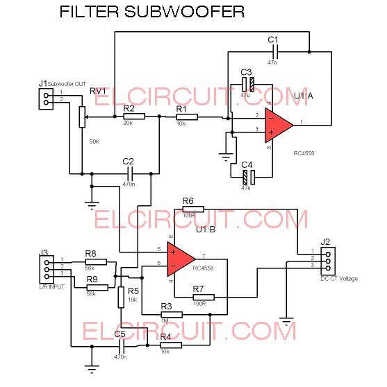
New Filter Subwoofer Circuit - Electronic Circuit

Solved In the notch filter circuit shown in the figure, | Chegg.com

Circuit Diagram and Filter 1.3-5W Power RF Amplifier Trans FM

Circuit Diagram and Filter 1.3-5W Power RF Amplifier Trans FM

Generator Schematic - Equivalent circuit diagram representation of the

30Watt VHF Amplifier Circuit for FM Broadcast Band